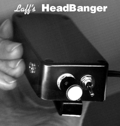
HeadBanger Headphone Amp Construction Kit
Making Your Own HeadBanger
Rev. 2, February 18, 2001
The Sound Professionals offer a
commercial version of this headphone amplifier.
You can build a high-quality portable amplifier to boost the output
of Sony's
MiniDisc portables. All parts are available at Radio Shack.
By Stephen H. Lafferty <[email protected]>;
After the euphoria over receiving my new Sony Minidisc bundle had partially
subsided, I noticed that the portable unit, the MZ-E40, has a rather weak
output. Measurements showed that it can only manage 80mV rms output and only
about 74dB SPL output from the phones. This is when recording at average
level with 8dB of headroom. In contrast, an orchestra can deliver more than
95dB SPL and they aren't considered headbangers. I tried all sorts of
solutions, but in the end realized that the only solution yielding the
headroom and quality worthy of the marvelous minidisc is to build a headphone
amp from scratch.
The end result is the "HeadBanger" which I will tell you how to build in this
article. It completely solves the level problem with plenty of room to spare.
It delivers up to 100-times the power that the E40 alone does. Noise is well
below the noise of the E40. Other specs are pretty good (see below). Sounds
wonderful. Runs on an internal NiCd battery or external charger. Estimated
running time is about 6-hours, depending on output level.
The HeadBanger is not for sale, but all parts are available at Radio Shack.
Cost of the parts is about $20 depending on what you can scrounge. The NiCd
battery and charger add $23. Caveats: Since it's not a kit, you have to be
pretty handy at constructing electronic projects to build it. Took me about
six evenings, but I had to do some development work on it. The attachments to
this article include:
This article offers construction details and debug tips. Sorry, I can't offer
to help you debug it, but I would appreciate comments (especially compliments
:-) .
Disclaimer
Protecting your hearing is your responsibility. Author is not responsible
for misuse or hearing damage. Do not use at extremely loud levels for
extended periods. Never listen at levels that leave your ears ringing or
leave your hearing temporarily depressed.
Specifications
The HeadBanger has adjustable gain up to 21dB, so it can deliver 95dB SPL
into headphones from the E40 at "average" record level. "Average" record
level is 8dB below digital max level. Output level with 80mV in is .95V.
   Size:             1 x 2 x 4 inches more-or-less
   Weight:           5 ounces (includes NiCd battery)
   Distortion:       0.2%
   Freq Response:    5Hz to >110kHz (-1dB)
   Max Output level: 1.7Vrms (loaded with RS Pro 25 phones)
   Noise:            Inaudible in quiet room
   Output Power:     375mW into 8-ohms
   Input Impedance:  33Kohms, minimum
   Running Time:     6-hours, est, high-cap NiCd, depending on audio level
   Circuit Desc:     Uses two LM386 power amp chips, 10-caps, 5-resistors.
   Controls:         Volume, On/Off switch
   I/O's:            Input pigtail, mini-phone out. DC power in.
Testimonial
Was out blowing leaves for hours today. Strapped on the E40, NoiseBuster
(active noise cancellation) and HeadBanger. [Three boxes on the belt--
RoboHomeowner. And they called me a nerd in high school for wearing a slide
rule on my belt. Har!] It was sweet. Grooving to the classic rock. Solid
bass. Silky highs. Super-smooth. Not a trace of distortion. It doesn't get
much better than this. This, is what the hoopla is about. At last I am at
peace with my minidisc bundle. Life is good.
Circuit Description
Audio-taper pot, R1, adjusts input level into two LM386 amplifier chips. The
LM386 is a low-voltage audio power amplifier, designed to operate on 4V to
12V. It has an internal 15K feedback resistor between pins 1 and 5 which
would set the gain at 20 (26dB). At this gain, the output noise is slightly
audible, so R2/R4 is added, effectively in parallel, to reduce the gain to 11
(21dB). Since the extra feedback is taken after the output coupling cap,
C3/C7, it also flattens the low end response. Distortion is reduced as well.
The feedback resistor must be AC coupled to avoid disturbing internal
biasing. C1/C5 decouple internal bias networks to improve power supply
rejection. Since audio-induced ripple on the supply is nonlinear, this
improves distortion performance as well as reducing hum in AC operation.
Output loading network C4/C8, R3/R5 stabilizes load impedance at high
frequencies to prevent oscillation.
The NiCd battery is charged through R6, which sets the charging current.
Since the HeadBanger only draws 10mA idle (25mA typical), the 12V AC adaptor
voltage is actually about 14.7V. The battery voltage during charging is about
8.4V. The 120mAH high-capacity NiCd needs about 196mAH of charging. [This is
projected from the 60mAH low-cap NiCd which is speced to charge in 14-hours
at 7mA.] With the HeadBanger off, 20 to 25mA is supplied, so the high-cap
battery will charge in about 10-hours. It might take twice that long with the
unit turned-on. The low-cap battery would charge in about 5-hours.
C10 reduces audio-induced ripple on the power supply. C9 bypasses the supply
at high frequencies, preventing oscillation. Note: Not shown on the schematic
is the separation of the input and output grounds. The ground wires from P1
and R1 are connected separately from other grounds to a point on the amp
board close to pin 2 of IC1 and IC2.
Design note: Due to low bias voltage at pin 1 of IC1 and IC2, the amount of
feedback voltage allowed there is limited. Although the amp could operate at
lower gain (lower R2/R4), this would increase feedback voltage. At low power
supply voltages this has the effect of causing a snap-back on large negative
half-cycles of the output signal. We chose the feedback value to just
eliminate the snap. Yet, it may be a contributing factor determining when the
battery is depleted. A higher value of R2/R4 (say 22K) might extend operating
time slightly and increase gain slightly. This would be at the expense of
making the noise slightly audible (but still well below the MZ-E40 noise).
Overview
The front.jpg and back.jpg pictures give you the gist of the HeadBanger.
It has a pigtail input. [That's jargon for a plug on a hard-wired cable
which hangs out of the unit.] Make the cable long enough to go around your
back in case you want to wear the HeadBanger on the other side from the
player. I needed this because I will be using a NoiseBuster as well. Since
the project boxes that are generally available don't have a battery
compartment, I included a NiCd to avoid having to open the unit to change
the battery. The belt clip is a standard part at Radio Shack (amazing!). The
complete parts list appears at the end of the article.
Precharging the Battery
If you have a 9V battery charger, charge the NiCd battery before
construction, since it will probably be discharged when you buy it. If you do
not have a battery charger, you can use the HeadBanger to do it after
construction.
Left and Right Reference
The left channel is on the tip of the miniplug (and socket). It may be color-
coded white in the inner conductor of a shielded stereo pair. I used yellow
wire for left. The rear volume control section is used for left (like "tip").
The right channel is on the ring of the miniplug (and socket). It may be
color-coded red in the inner conductor of a shielded stereo pair. I used
green wire for right. The forward volume control section is used for right.
Drilling the Case
(Why does the unpleasant part always come at the beginning?) Well, in this...
er... case it's not all that bad. The only thing is, this is a miniature
project, so accuracy matters. Fortunately, plastic is easy to drill. The
Radio Shack project case is plastic with a metal cover. The positions and
sizes of the holes are shown in holes.gif. This drawing is shown as if you
are looking into the box with the metal cover removed. All holes are 0.55"
down from the open top.
The locations of the holes are chosen to maximize clearances inside. The
front panel holes also center the controls. In retrospect, I find the volume
and switch a little too close together (but it works fine). The volume cannot
go any closer to the side, however. In fact, it has almost zero clearance
now. You could move it 1/16" farther from its side and the switch 1/8" in the
same direction. This might unbalance the appearance of the front panel,
however. By the way, as described below, the volume pot must be trimmed
before it will fit.
Mark the holes carefully. When measuring to a side around a rounded corner,
use a straightedge held against the reference side. Mark the holes by
scratching with a sharp object. Then you need a "center punch" to start the
drill. To do this with the brittle plastic, I heated a nail (held with
pliers) over the stove. For drilling, the case must be held in a vise. Don't
clamp too tightly! Radio Shack sells a cheap vacuum-held vise which worked
well. Drill carefully. It goes through the plastic quickly.
The large 7/16" hole for the DC jack gave me a bit of a hassle. Since it is
such a large hole for this box, I first drilled a quarter-inch starter hole.
When I applied the 7/16 bit, it rattled around a little and suddenly grabbed.
It then ripped through the hole in a flash. The edge where it grabbed was
rough. In retrospect, perhaps it would have worked better without the starter
hole. One thing's for sure: I'm glad that the box was securely in the vise
and not in my hand!
Mounting the Chassis parts
Cut the shaft of the volume control to a length of 3/8" past the bushing
from which it protrudes. To do this, mark the cutting position and put the
end of the shaft in a vise. Since I was using a cheap plastic vise, I had to
put something in the other side the vice grip to balance the load on the
grip. Do NOT put the body of the control in the vise. Use a jig saw with a
fine pitch blade to cut the shaft. I find I have to be very careful to get a
square cut. Fortunately, the squareness doesn't matter too much here, but it
should be decent.
The volume control must be trimmed before it will fit in the box. Use side-
angle cutters to remove the phenolic parts protruding with the taps. These
are on the opposite side from the six main connection lugs. Be very careful
not to crack the phenolic inside. I cut tangent to the case of the pot
towards the rivet hole. Also remove the keying tab protruding toward the
front panel. Grip it with needle-nose pliers and bend. It will break off. All
six solder lugs for the pot should be bent down as much as possible to
maximize clearance to the metal cover of the box. Leave nothing on the
threaded shaft between the pot and the panel unless you want to take
advantage of the tip below. After reading the tip, place the washer and nut
on the shaft and tighten with the solder lugs up. ["Up" is towards the open
side of the case.]
TIP: You may want to ground the body of the volume control. I found out later
that without it, the unit picks up hum from your hand when it is on AC power
and you adjust the volume. To ground the control, wrap one turn of small,
solid, bare wire around the threaded shaft before mounting the control. Leave
about 2.5" of wire free for now.
Turn the volume control fully counterclockwise. Unscrew the setscrew of the
volume knob and place the knob on the control as close to the front panel as
it will go. Point the knob to the 7:00 position and tighten the setscrew.
Put two layers of electrical tape on the underside of the metal cover where
the lugs of the volume control are. (There is very little clearance.) Leave
room for the grounding lug to make contact with the metal cover. See the
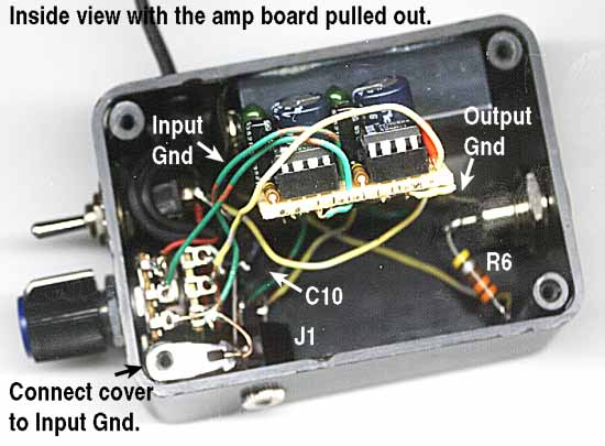
pullout.jpg figure to locate the grounding lug.
Mount the output jack (J1) with the ground lug up at about a 30 degree angle
so that the tip and ring lugs are both easily accessible. Tilt the ground lug
toward the front panel where the volume control is. The bottom-most lug is
the tip (left channel) and the upper lug is the ring (right channel).
Mount the DC jack (J2) with the ground lug toward the battery position. Bend
the ground lug toward the battery so that it projects no farther into the box
than the other pin on the jack. Mount the switch, aligned vertically, so it
swings at right angles to the metal cover. Work a 3/8" outside diameter
grommet into the hole for the input pigtail. Hold off mounting the battery.
Soldering Instructions
In the following instructions, "connect" means to crimp a wire onto a lug.
When all connections have been attached, we will say to "solder" the
connection. In general, only the last connection can be "tack" soldered; and
then only when necessary. "Tack" soldering is using the solder to physically
hold a wire without crimping it.
About the Hookup Wire
I used standard telephone hookup wire. The only drawback was that the
insulation tended to melt-back quickly during soldering. It also is not
tinned. I recommend solid wire.
Wiring the Chassis
We need to wire the chassis completely before attempting to install the amp
board. If you do not plan to follow the chassis wiring below, at least make
sure that you DO NOT connect the volume control ground and cover grounding
lug to the other chassis part grounds. As discussed below, we need to
separate the input ground from the output ground to prevent oscillation.
Trim the length of the leads on the 9V battery connector to 2.5". Connect
the positive (red) lead to the lower lug of the switch. The battery should
not be connected. [We assume you are using a SPST switch. If you have a SPDT
switch, ignore the bottom lug and use the two upper lugs.]
Trim both leads of 330 ohm R6 to 1/2". Bend one lead 90 degrees in the
middle and solder it into the center pin of DC jack J2. Solder a wire onto
the other lead at about 3/16" from R6. Trim the solder joint and bend the
resistor back into the corner as shown in figure pullout.jpg. Route the wire
down along the bottom of the case and connect it to the lower lug of the
switch. Solder the connection.
Connect C10 between the upper lug of the switch and the ground lug of output
jack J1. Position C10 with its leads pointing up as shown in figure
inside.jpg. Be sure that the negative terminal is connected to J1. The
negative terminal is the one marked with a minus sign and arrow. Solder at J1
but not at the switch.
Connect a wire from the ground lug of DC jack J2 to the negative lead
of C10, about 3/16" away from the cap. Route this wire straight down from J2
to the bottom of the box and then up by the front panel around back of the
C10 and up to its lead. Connect the negative lead of the 9V battery connector
to the same place on the negative lead of C10. Solder the connection there.
The input grounds must be kept separate from the output grounds, otherwise
the unit will oscillate. Tied to the input ground are the input pigtail, the
volume control and the lug contacting the metal cover. The pigtail is a
miniplug and cable which is the input to the HeadBanger. I cut mine from an
old pair of headphones. If you can't scrounge one, a Radio Shack cable is
in the parts list. I made mine 28" from the tip of the plug to the side of
the case. Thus, I can wear the Minidisc on one side and the HeadBanger and
NoiseBuster on the other. If you know that you will keep the minidisc and
HeadBanger together, perhaps 12" would be better for the pigtail. Just make
sure that it has a 1/8" stereo miniplug on one end and open wire on the other
end. the initial length will need to be about 4" longer than the final
length.
The pigtail should have two shielded cables. Push the open wire end through
the input pigtail grommet. Pull 12" or so through and tie a knot about 3"
from end of the wire. Tighten the knot and pull the excess wire back through
the grommet until the knot is snug against the grommet. Cut the length of
cable inside the box to 2" and strip 3/4" of the outside insulation. Be
careful not to cut the fine strands of shield (ground) wire. Separate and
twist the shield strands into two bundles and then twist the two bundles to
make one ground wire. Strip 1/4" from each inner conductor. Connect the inner
conductors to the two lugs of the volume control closest to the switch. The
left channel (tip) goes to the lug farthest from the front panel. Connect the
right channel (ring) to the lug closest to the front panel. The inner
conductors may be color coded, white for left and red for right. Solder the
two input connections.
If you added the ground wire when mounting the control, route it through the
two lugs on the opposite side of the control from the connections we just
made. If you did not add the ground wire, connect a 2" bare wire to the
volume control lug closest to the cover screw and pass it through the other
volume control lug on that side. Then route the wire down behind the control
and connect it to the ground wire of the pigtail. Solder at the pigtail only.
We need a lug to contact the metal cover like the one by the volume control
in figure Inside.jpg. I drilled-out one lug of a terminal strip for mine.
Radio Shack sells terminal strips (part no. 274-688), but if you have to buy
one, they have lugs too, such as part no. 64-3030. Since I haven't tried
those, you would have to make sure it fits.
Connect a short, bare wire to the cover lug and the rear ground lug of the
volume control. Solder the two ground lugs on the volume control and the
cover lug. Position the cover lug so that the cover screw next to the volume
control will pass through it as in figure Inside.jpg. Bend the soldered end
down a little so it will clear the cover. The chassis wiring is now complete.
Now we will install the battery. Make sure that the power switch is off
(towards the open end of the box). Attach the 9V connector to the battery.
Orient the battery so that the leads from the 9V connector point away from
the side of the box. Use side-angle cutters to trim any part of the 9V
connector which protrudes above the battery. Next, we will need a warmed hot
glue gun. In a very quick operation, apply one strip of hot glue to the side
of the battery next to the wall and immediately press the battery firmly
against the wall. It should be snug against the screw post near the bottom of
the battery and also resting on the bottom of the box. Hold it tight for 30
seconds or so. If you need to replace the NiCd battery, you should be able to
pry it from the wall with a screwdriver.
Building the Amp Board
This is the fun part: real hands-on electronics! But as you can see from
figure Inside.jpg, there is very little clearance for the amp board. In fact,
I had to try a few different component layouts, to find one which would fit.
So I recommend that you try to build it just as it is shown. Figure
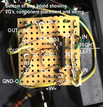
Inside.jpg gives you the top view and figure Boardwir.jpg gives a bottom
view. It also has component designators and the external connections are
shown. Cut a piece of perf-board so that there are 11 x 12 holes visible.
I used a jig saw with a fine-tooth blade, cutting along a row of holes. Be
sure that you count-over one extra row so that the number of holes left is
the right number.
The trick to locating components is finding the lead holes after spotting the
reference designator. Usually, there are two leads. They may be spaced
vertically or horizontally. The spacing is .1, .2 or .3 inches. (Holes are
spaced every .1". For example, take R4 (the only designator in black) in the
upper right corner. The leads are spaced .3" apart horizontally. C3 at the
lower middle is a little harder. Its leads are arranged vertically, tying to
C2 and to pin 5 of IC1.
Pins 1 and 5 of each IC (integrated circuit) are labeled in Boardwir.jpg.
FROM THE BOTTOM, the IC pins are numbered in this order:
8  1
7  2
6  3
5  4
Pin 1 is marked on the chip itself by a dot (see Inside.jpg). Pin 8 is not
connected in this design. Notice that R3 and R5 are stood-up, transistor
radio style. You can see them end-on at the upper-right of the green caps in
figure Inside.jpg.
In boardwir.jpg, the right channel occupies the upper half of the board and
the left channel is on the lower half. The two channels are laid out
identically. A ground bus forms a "T", with the top of the T running between
IC1 and IC2. The only place a wire needed insulation on the board is where
the +9V bus crosses the ground bus. Notice that there are two external ground
connections to this same ground bus. One is the Input ground (GND-I) and the
other is the Output ground (GND-O). The Input ground wire comes to the top of
the board and pokes directly through to its connection at the place to which
the GND-I arrow is pointing. The two input wires also come to the top of the
board and pass through for strain relief. They connect directly to IC socket
pins which are very small.
The easiest way to solder to the IC socket pins is to bend them flat against
the board and run the wire beside them. Then tack-solder. You can also run
the wire past a vertical pin and tack-solder. The ground bus runs over some
pins bent flat and soldered. It is not easy to crimp wires onto the pins.
In most cases, you will not need hookup wire. Use the component leads
themselves to make connections. After inserting a component, pull its leads
out to secure it. Then insert components which attach to it and twist leads
together. Solder and trim leads as you go, keeping an eye on the schematic
(schem.gif) so you solder only after all connections to a point are made. You
will also need to follow the schematic to insure that you are wiring
correctly. The pictorials are not always obvious.
To get started, insert the socket for IC2 and bend out leads at opposite
corners to hold it. [Note: do not insert the IC's in the sockets until the
end.] Insert R4 and bend the lead sharply over to pin 1 of IC2. You may need
to trim the lead to get it to contact pin 1. Solder the connection. Now
insert C6. Make sure that all caps with polarity markings on the schematic
are inserted in correct polarity. C6 has its negative lead marked with a
minus and an arrow. That lead should be away from R4, leaving the positive
lead towards R4. Twist the adjacent leads of C6 and R4 together, solder and
trim. Continue with the other components.
You may be able to use the lead of C9 to connect ground from pins 2 and 4 of
IC1 to the same on IC2. Use bare wire to complete the bus to R3/C1. After the
amp board is wired, add 5" external leads for the following connections:
   IN, right   - Enters from top for strain relief.
   IN, left    - Enters from top (under C9) for strain relief.
   OUT, right  - From bottom.
   OUT, left   - From bottom.
   +9V         - From bottom, at C9.
   GND-O       - From bottom, at R3/C1.
   GND-I       - Enters from top at place pointed as GND-I. Connect to gnd.
Complete the amp board by inserting IC1 and IC2 into their sockets. If you
are concerned that your wiring of the IC pins may be wrong, you could leave
out one of the chips until the other channel is tested good. This way, a
mistake common to both channels cannot damage both chips. It is easy to take
the wrong corner as pin 1 because the view from the bottom is the reverse of
the view from the top.
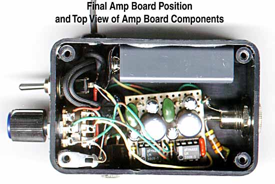
Installing the Amp Board
Wire the amp to the chassis so that it can be pulled-out as shown in figure
pullout.jpg. In fact, allow the board to be oriented vertically. With the
board in this position (IC's up), resting on the battery, trim the length of
the Output ground (GND-O) lead of the amp and solder it to the ground lug of
the DC power connector.
Note: When trimming the length of the amp board leads, leave a little slack,
but not so much that they are meandering. Arrange the leads so you can easily
rotate the amp to horizontal and press it down into place.
Make sure that the switch is in the off position (towards the open end of the
box). Then trim and solder the +9V lead of the amp to the top lug of the
switch. Similarly, trim and solder the two output leads to J1. If you
oriented the jack as described in "Mounting the Chassis Parts," the left
channel (tip) lug is the one closest to the bottom of the box. The right
channel (ring) lug is the next one up. You can look inside the extra jack to
verify.
Trim and solder the amp Input leads to the two middle lugs of the volume
control. Left is attached to the rear section of the control. Finally, solder
the Input ground (GND-I) to the volume control lug attached to the cover
ground lug.
Congratulations! You have completed basic assembly of the HeadBanger. But
don't go pushing the amp board in yet. We need to test this puppy.
Charging the Battery
While you can operate the HeadBanger on the AC supply, testing would be a
little cleaner on a fully charged battery. If you did not ground the volume
control (as in the TIP above), the unit may pickup AC hum when operated on
the AC adapter.
To charge the battery, first configure the connector on the AC adaptor. Tip
should be (+) positive. Use the connector adaptor for 5.5mm OD and 2.1mm ID.
Turn the HeadBanger off, plug the AC adaptor into the wall outlet, and insert
the its plug into the DC jack on the HeadBanger. Charging will take about 10-
hours with the high-capacity battery. [See Note 10 on the parts list.]
Testing the HeadBanger
Attach a pair of headphones to J1 and plug the pigtail into an audio source.
Set the volume control to the 12:00 position (half-way). Put on the phones
and switch the unit on (away from the open end of the box). You should hear a
loud click. (Sorry about that; the output caps have to charge.) With the
audio source off, you should hear little, if any, noise. Whirring or buzzing
might indicate oscillation. If all is quiet, turn on the audio. It should
sound excellent at all levels. You may need to adjust the output level of the
source so that it does not distort. The MZ-E40 does not seem to distort at
max gain setting, so that is where I tend to run it. Distortion at normal
levels might indicate oscillation.
If the HeadBanger sounds good, I would still recommend probing the outputs on
J1 with a scope to make sure there is no oscillation. Test with high and low
level signals and at high and low settings of the volume control. Testing
with an oscillator would be best. Examine the negative half-cycle of a high-
level signal closely. Before the design was debugged, it tended to oscillate
in the 1MHz to 1.4MHz range. If you do not have a scope, a listening test
should suffice.
If the critter tests okay, bravo! You have almost completed a challenging
project. If you find a problem, see "Debugging the Sick Puppy," below.
Final Assembly
With the unit turned off, carefully work the amp board into a horizontal
position and down into the box. Rather than just pushing the board all the
way, also pull down on the amp's external leads under the board. Try to make
sure that any bare wire on the lead connections does not short to other
points under the board. Push the board down until it is below the DC jack
lugs and the corner of Output jack, J1. The external lead wires will hold it
firmly in place. Arrange the input leads coming from the top of the board so
that they will run along the grounded metal cover when it is put in place.
Make sure the unit still works okay. Then turn it off and attach the metal
cover with the four screws supplied with the case. Do not over-tighten--just
snug. Follow the instructions on the Universal Belt Clip package to attach
the belt clip as shown in figure back.jpg. I positioned it so that the end of
the clip is about 1/16" below the front panel. While the instructions say
that you can use it immediately, I waited for 72-hours (three long days!)
before clipping it on my belt, to allow the adhesive to cure completely.
If you have made it this far, you now deserve a Summa Cum Laude in miniature
project building. This is what it feels like to be a Japanese engineer ;D
Let me know how you like it. Happy listening. (Take care of those ears...)
Debugging the Sick Puppy
Well, if you are reading this, you are not a happy camper. Sorry that it
didn't work on the first try, but then few things do. Don't give up, it's
probably just a wiring error or a short. Here are some suggestions:
If You Can't Get Any Output
First, check the obvious: Plug the headphones into the audio source to make
sure it is working. Make sure that the switch is on (away from the open end
of the box) and that the volume control is clockwise. [Leave it at halfway.]
Use a multimeter to verify that there is 9V on pin-6 of the IC's and that
pin-4 is at zero. [What we refer to as "9V" is actually lower due to the NiCd
battery. Expect about 7 or 8 volts.] Use the DC connector ground lug for a
reference. If you are using a scope, attach its ground to the that same
point (not the Input ground). Check pin-5 of each chip to see if it is at
about half the supply voltage. Pins 2 and 3 should be at zero.
Is There a Short Under the Amp Board?
The insulation on the leads going to the amp board should extend close to the
points at which they are soldered. If not, the bare part of a lead may have
shorted to other connections when the board was pushed into place. To check
for this, pull the board up carefully and see if any bare lead wire is
getting close to other connections.
Wiring Check
Compare your wiring to boardwir.jpg and schem.gif. Compare the top view to
inside.jpg. [Make sure your viewer shows a large, zoomed-in view of the
board.] Trace the wiring point-to-point vs the schematic (Schem.gif). Look
for shorts. Make sure that the polarities of C1, C2, C3, C5, C6, C7 and C10
are correct. Check the component values, especially the resistors. R2 and R4
are Brown/Gray/Orange. R3 and R5 are Brown/Black/Black. Check the chassis
connections against inside.jpg, pullout.jpg and schem.gif.
Oscillation Problems
The unit will definitely oscillate if:
- The input ground is not separated from the output ground. Make sure
that these are not shorting at the negative lead of C10 near the pigtail
ground wire. If you have not wired the grounds exactly as described in the
text, do so. This isn't boiler-plate; it's critical.
- C9 is not on the amp board. IC1 and IC2 need HF power supply bypassing
very close to their power and ground pins. You could try adding another .1uF
cap bypass under the board. Note: In the photo, C9 is red. I used a smaller
one that I already had. Yours will be larger and green like my other ones.
- The output loading network R3/C4 or R5/C8 is not correct. The amp
needs a stable load at high frequency. Make sure that these components are
the right ones and are connected properly. If the oscillation stops when the
headphone is unplugged, this may indicate a problem with the loading network.
Note: Some fluorescent lamps generate 50kHz noise in a big way. Apparently,
they use a switching supply. My Service Merchandise magnifier lamp (with
Circleline bulb) does this.
Checking Current Consumption
High idle power supply current might indicate oscillation or other problems.
Normal current with no signal is about 10mA. With the battery in-place, it is
not very easy to remove and reattach the battery connector. To measure the
current, though, you can use a flatblade screwdriver to pry the connector
away from only the top (negative) terminal of the battery. Slip a small piece
of paper between the connector and the battery. Set the multimeter to read
current on a 100mA scale. [Some meters require the red test lead to be moved
to a different jack to measure current.] Then, with the HeadBanger switched
on, hold the probes on the battery terminal and the connector terminal to
read current. Remove the paper and reattach the connector. Slip the
screwdriver down along the top the connector to press the lower part of the
connector against the battery, in case it has loosened.
If All Else Fails
Don't call me ;) (Sorry, but this project has already gone far beyond the
amount of time I had for it.) Consider taking the unit and all of the
documentation in this article to a hobbiest or ham friend or to a local
repair shop.
I sincerely hope that it turns out well for you. --shl
Parts List for HeadBanger Headphone Amp
(All parts are available at Radio Shack {RS}.)
Qty     Description                 REF  RS Part No.      $ ea   $     Note
===========================================================================
1  100K stereo control-audio taper  R1   271-1732                1.99
1  1/8" phoneplug/cable for pigtail P1   42-2387                 3.99   1
1  1/2" knob, blue tip            [R1]   274-403  (2ea)           .99
2  LM386 IC power amp          IC1,IC2   276-1731         1.19   2.38
4  Cap, 10uF 35V           C1,C2,C5,C6   272-1025          .59   2.36
3  Cap, 470uF 16V            C3,C7,C10   272-957           .99   2.97
3  Cap, 0.1uF 50V             C4,C8,C9   272-1069          .79   2.37   2
2  Socket, 8-pin dip         [IC1,IC2]   276-1995 (2ea)           .59   3
1  Perf board                            276-1395                2.19   4
1  Case ~3x2x1. Al cover.                270-230                 1.99
1  Resistor, 330, 1/2W              R6   271-1113 (5ea)           .49  10
2  Resistor, 18K, 1/4W           R2,R4   RSU-11345105 (5ea)       .49   5
2  Resistor, 10, 1/4/W           R3,R5   271-1301 (5ea)           .49
1  1/8" stereo phone jack OC        J1   274-249  (2ea)          1.99   6
1  9-volt battery connector       [B1]   270-325  (5ea)          1.39
1  DC jack 5.5mm/2.1mm              J2   274-1563                1.69   7
1  9-volt hi-cap NiCd battery       B1   23-299                  9.99   8
1  AC adaptor, 12V 500mA            A1   273-1652               12.99
1  Belt Clip, universal                  43-168                  1.99?  9
1  Grommet for pigtail, 3/8"             64-3025 (assorted)      1.49
1  Switch, submini SPST             S1   275-612                 2.89  11
1  Lug from terminal strip               274-688 (4ea)           1.29  12
Notes:
- I cut a phone jack and cable from an old pair of headphones instead.
Leave enough cord so it can go around your back.
- The RS part is a bit large. I used a smaller one I had on hand for one
of them.
- The RS part has short leads which aren't very easy to solder-to through
the vector board. If you can find ones with longer leads, do it.
- I used the standard perf board with holes every .1" and no solder pads.
Picked it out at RS--I think this is the right part number.
- This standard resistor must be ordered at most Radio Shacks. You can
substitute a 22K (P/N 271-1339). This will give slightly higher gain and
possibly longer running time at the expense of slightly higher noise.
- It's a good thing these come 2-each because the first one I put in was
bad. Before installing, check yours to make sure that you don't lose
connection on either channel when tugging lightly on the phone plug.
channel when tugging lightly on the phone plug.
- I wished that I could have found a smaller one. RS has others, but they
have an internal switch that isn't needed. If you use a different one,
make sure that the AC adaptor fits it.
- I actually got stuck with their lower-capacity battery, since the hi-cap
was sold out. Pity, since the hi-cap is only $1 more and has twice the
capacity (120mAh). Probably can withstand quick charging better too.
- RS's universal belt clip is a real jewel! Comes with permanent adhesive.
Just perfect for this (and other) projects.
- This resistor sets the charging current of the NiCd battery. The 330 ohm
value gives about 25mA which will charge the low-cap NiCd in 5-hours or the
high-cap NiCd in 10-hours. If you use 150 ohms, it will cut the time in
half. I would not recommend this with the low-cap NiCd and don't know
about the hi-cap one. The low-cap NiCd package said 7mA for 14-hours, so
even doing it in 5-hours may shorten battery life. I chose 5-hours
because many NiCd's are being charged at that rate. Note: The charger
delivers 14.7V at this light load. The battery is about 8.4V during
charge.
- I used a switch I already had. Picked this one as the closest match out of
the RS catalog. Make sure that it fits the box okay and that the sleeve is
long enough to go through the thick plastic wall and still have enough
turns left (three) for the retaining nut.
- Actually, all we need is a lug with which to contact the metal cover. I
drilled one out of a terminal strip. If you have to buy one, check Radio
Shack's lug hardware (such as 64-3030) to see if they have a lug that
fits. (See figure inside.jpg --lug in lower left corner of box.)
Addendum
This addendum describes an important modification to the headphone amplifier
described in my construction article, "Making Your Own HeadBanger."
In using the unit on a Snapper riding lawnmower, I found that the ignition
noise from the engine was being picked-up by the HeadBanger. The fix for this
problem is to add a grounded metal plate to the bottom of the chassis. This is
easier and more effective if you do it before mounting the components on the
chassis. The shield seemed to fix the problem, but I was only able to test it
once, since cutting season ended. If you encounter further problems, some more
ideas are given at the end.
Note: If you did not ground the volume control body as was suggested, in the
article, you should do so now. (See article.)
Adding the Shield
Cut an a rectangle from thin aluminum as large as will easily fix on the
bottom of the chassis. If you are doing this before mounting components, this
will be easy and you can afford to leave 1/8" of clearance to walls and posts.
If you have already built the unit, as I have, start with a rectangle of
1 3/8" x 1 9/16". I used the metal from a soda can. This is not an ideal
choice, since it seems to have an insulating coating. Gently pull the amp
board out without breaking wires. Try not to let wires bend any more than
necessary. It is not necessary to unsolder the board. See if the shield will
fit under the area where the amp board usually sits. You can feed it in from
the wall where the output jack is mounted, curving it around the corner of the
wall and the bottom. Depending on how solidly the battery is pressing on the
bottom, you may need to trim the shield.
Remove the shield and make a hole in it, large enough for a 4-40 screw, 1/4"
from a corner. We will be looking into the chassis with the output jack wall
at the bottom and the DC jack to the right. Orient the shield with the hole in
the lower right corner. Push a short 4-40 screw through the hole, up from the
underside of the shield.
Cut a 4" length of insulated hookup wire. Strip and twist a loop around the
screw, next to the top side of the shield. Tighten the screw with a washer and
nut. Cover the shield with electrical tape, except for the corner with the
screw. Trim excess tape from the edges.
Thread the shield into the bottom of the chassis. The corner with the screw
should be in the lower right corner, under the 330 ohm DC jack resistor. Run
the wire along the bottom of the chassis, then up to area of the volume
control. If you have already mounted the control, attach the wire to the
ground lug of the volume control (closest to the output jack wall) and solder
it. Otherwise, attach it later when the control is mounted.
Carefully push the amp board back in and test the unit. Re-attach the cover.
If You Encounter More Interference
If you should have more interference problems, you could try this idea: Add
220pF caps (RS# 272-124) from the wiper of the volume control to ground. You
can mount these on the control itself. The wiper is the center lug and the
ground is the lug attached to the free ground lug.
HeadBanger Grounding
Since there have been questions, I want to clarify the HeadBanger grounding. Some folks have been understandably confused by what we mean by "keeping the input and output grounds separated." The idea behind the grounding is to prevent output currents from flowing in the input ground. This causes oscillation.
The input and output grounds do come together, but only at a single point on the amp board. In the ground.jpg pic, the ground bus under the board is marked in red. Notice that the output ground connection (GND-O) is at the left and the input ground connection comes in from the top side, right at the point marked "GND-I".
FAQs about HeadBanger grounding:
- It is stated in many places that the output ground and input ground need to be separate. However it also says: "Notice that there are two external ground connections to this same ground bus. One is the Input ground (GND-I) and the other is the Output ground (GND-O)." From this it sounds like GND-I and GND-O are connected together, on the amp board. Hence my confusion.
Answer: The input and output grounds are separate EXCEPT for where they come together under the ground board.
- Which parts should be connected to the input ground and which to the output ground?
Answer: The input ground goes to the input pigtail (P1), volume control, pins 2 and 4 of both IC's, and the case. All others are output grounds.
- The grounds are connected on your board. In boardwir.jpg, is there a wire under the black thing between labels "IC1" and "IC2"?
Answer: The "black thing" is a piece of tubing used to insulate the +9V wire. Yes, the ground bus runs under it. Please refer to the attached ground.jpg.
- In boardwir.jpg, are the grounds on the left, input grounds?
Answer: No, notice that the output ground is connected on the left. On my board, the external wire for input ground comes in from the topside exactly at the point marked "GND-I".
- Your plans call for "separate grounds" for Input and output...should there also be a separate ground for everything else in the schematic? Ultimately, they would all end up going to the 9V battery anyway, right?
Answer: You don't need separate grounds for everything. We just need to group the output grounds together and then the input grounds together. Then connect the groups at one point. While they all "end up going to the 9V battery" eventually, the important thing is to prevent the high currents in the output grounds from flowing through the input ground wires. Things connected to the input grounds are sensitive to the small voltages which would be induced in the input ground wires by the output currents.
Modified Koss Earplugs Instead of HeadBanger
The HeadBanger was designed to increase portable minidisk output level, especially when used with active noise reduction phones. A completely different approach is to use earplug style phones. Until recently, I did not consider those because: (1) The units I was familiar with had poor fidelity. (2) I was concerned about earwax mess. and (3) I thought that it would not be comfortable enough to wear for hours at a time. Then I saw the article by Chu Moy at the site:
http://headwize.com/projects/cmoy4_prj.htm
I tried the Koss plugs with Moy's cushion-modification and was pleasantly surprised. The fidelity was decent, although not great. There was no problem with earwax. (With Moy's approach, replacement cushions are also plentiful.) Comfort was adequate. The best part is that the noise reduction is WAY beyond anything I can imagine from active cancellation. An added benefit is that the Koss Plugs are more sensitive than the other phones I have tried. This, combined with their noise reduction, eliminated the need for using the HeadBanger amp with the MZ-E40 portable minidisk player.
Some issues about using the Koss/Moy Plugs:
- The low-frequency response depends on the quality of the seal between the Plugs and the ear canal. The seal, even with Moy's mods, takes a minute or so to develop. This is apparently because the earplug foam is somewhat compressed as it is pushed-in. It gradually relaxes against the confines of the ear canal, forming a seal. So the low frequency response doesn't seem good in a quick test.
- After the foam relaxes against the ear canal, there is noticeable pressure. I did not find it objectionable. In any case, it is what the Flent's earplugs do. (The original Koss foam is softer, but doesn't seal well.)
- I used a Dremel to drill the holes, I think. (See Moy.)
- After you cut the Flents Earplugs to length, they will have a shiny end and a regular foam end. It works better if the shiny end is towards the ear.
User Questions & Comments
Questions
From Todd Matherne:
I recently decided to start using a personal headphone monitor system on stage, to replace my floor monitor. I only have a few radio shack headphones. I noticed that the amp drives the headphones rather hard. I can not turn up very much, before the headset diaghragms start to rattle. I am however using the 22k Resistor, instead of the 18k. I noticed in your document that "noise" could be a factor.
I would like to include a tone ckt to take out some of the bass frequencies on stage. I am a gigging guitarist, and I simply and tapped off of the stereo mix of the sound board.
Anyway, I have a few basic questions:
How do I measure the impedance of my headphones?
Am I driving the wrong type of headsets?
I didn't hear any noise last night, when I prototyped, but just explain in detail the grounding thing.
Do you have a simple tone ckt to equalize the bass and treble?
Steve Lafferty replies:
Please see the blurb "HeadBanger Grounding", about the Grounding Thing. Sorry that you are experiencing a "rattle" in the headphones. Could it be that they just aren't able to take the level? I guess you already checked that by driving the phones from another source. The HeadBanger should be able to drive any phones with 8-ohms or greater impedance, so it should not be an issue. The 22K resistor instead of the 18K shouldn't make much difference either.
I'm sorry that I can't supply bass and treble circuits for the HeadBanger, but taking out the bass frequencies is easy: Just insert a 0.005uF cap between the input jack and the volume control pot. (Best placed near the pot.) This cap value will roll-off 3dB at 300Hz, giving about 10dB rejection at 100Hz. If you want less bass rejection, increase the cap and vice versa.
From Lawrence in the UK:
Having bought the impressive Creative Labs Jukebox player (6GB hard drive), I would appreciate more volume from the 'phones output and plan to build a headphone amp.
Please can you tell me whether this circuit is designed to be plugged into a "line out" socket rather than the headphone socket. The "line out" will give better sound quality especially with the Creative because they (according to a review) roll off the bass on the headphone socket below 60Hz.
Steve Lafferty replies:
Yes, it should work fine on the line out. By the way, if the bass rolls-off because of a small output coupling capacitor, the high-Z load of the HeadBanger on the headphone output would solve the rolloff problem. But, as you mentioned, the line out should still give better quality.
From Lawrence in the UK:
Happy new year. I want to thank you for the circuit details for the headbanger. The job was done over the holiday. Its suberb and just what was I needed - should have made one years ago for my Sony Discman and it is now perfect for my new Creative DAP jukebox. The intrinsic sound quality with my Koss MAC 5 headphones is greatly improved (more control, dynamics and detail).
There is just the faintest trace of radio breakthough and hum but its not a problem. This may be sorted when I complete the screening and socketry. The job came in about at about $21. What fun for so little financial outlay!
Should I visit Roswell I will buy you a few beers. Thanks.
Steve Lafferty replies:
>trace of radio breakthough and hum
---I trust that you saw the bit about grounding the volume control case and the addendum about adding a shield under the board. For the RF interference, you could add the 220pF caps mentioned in the section, "If You Encounter More Interference". (Smaller caps could be used if you are concerned about the effect on response.)
>Should I visit Roswell I will buy you a few beers. Thanks.
---In the meantime, I will drink a Guinness in your honor ;-) It was nice to hear from you.
From Mark Mander:
I am a newbe and have a few questions I hope you can help me with.
Can I use your headphone amplifier on a Apple G4 sound output ( Full Scale Output level: 3.0 V peak to peak with a 5 kilohm load )?
Will a 600 ohm sennheiser headphone, which I have work on your output?
Steve Lafferty replies:
The HeadBanger should work okay with the Apple output. (If you are planning to buy a commercial version, make sure that you get the model with the volume control.) The headphones should work on the HeadBanger output.
One caveat: The 600ohm impedance of the headphones is a bit high. This is no problem, but it might imply less voltage-sensitivity than typical. The HeadBanger max output is 1.7VRMS (4.8VP-P). You might want to set the speaker-output of a stereo to this level and connect the headphones to see if it will be loud enough for you. I don't really anticipate a problem, though.
From Greg Campbell:
I just built the headbanger but am having problems with it distorting at just about any volume. What do you suggest I try looking at? The volume of the input source is down as well and I still get a sound like the unit is over driving? Why? Your help is appreciated. Thank you.
Steve Lafferty replies:
Sorry that you are having a problem with it. It's difficult to troubleshoot remotely, but I'll try to help:
First, it may sound trite, but you should do a thorough check of the wiring against the schematic. The most effective way is to use a high-lighter to mark the lines on the schematic as you trace them on the unit.
There has been some confusion on the grounding. Please see the "Headbanger Grounding" article below and the attached pic.
The distortion could be caused by oscillation. The best way to check for oscillation is with an oscilloscope. With audio applied, see if there is a high frequency (perhaps 1MHz or so) signal riding on the audio waveform. If you don't have access to an oscilloscope, just make sure that your ground wiring complies with the grounding described in the original article and the article below.
Is the problem happening on both channels? If so, there may be a common cause...
If you have a multimeter, you can do some voltage checks:
- Make sure the 9V supply is approximately 9V.
- Check the voltage at pin-5 of each LM386. It should be about half the power supply voltage (4.5V).
- Are C3 and C4 0.1uF caps? If they were say, 10uF, it might cause distortion.
I hope that this helps, Greg. If not, take heart: Lots of these have been built. There's probably just one little thing wrong in there and it will sound great when you find it.
From Fred Harmon:
Do you have any suggestions for converting the Headbanger to work off a vehicle's 12 volt electrical system? Seems like I would need to both regulate and filter (ripple) the power source. Can you offer any advice?
Steve Lafferty replies:
First, instead of using the HeadBanger, you may wish to consider the in-ear phones discussed in the "Earplugs" blurb. I will answer your question, though:
If you plan to use the HeadBanger alone, as well as on the cycle, you could just apply the vehicle power directly to the AC adapter jack of the standard design. The 14V power is close-enough to the 14.7V it expects there. The NiCd battery regulates the voltage.
But I assume that you want to mount it, or otherwise don't need the NiCd battery. In that case, you could use an LM386N-4 chip instead of the LM386N. The Dash-4 part operates up to 18V and can withstand 22V. Eliminate the NiCd and change R6 to 100-ohms. With the 470uF bypass cap, this will provide 80dB of power supply rejection at 100Hz, including the 50dB provided by the chip.
From Fred Harmon:
I built the unit this weekend and tested it (without a battery) directly connected to the bike's electrical system through the 330 ohm resistor. I measured the voltage at the chip and it was about 10.9 volts. I think I can probably just increase the size of the resistor to say 400 or 450 ohms and that should knock it down enough that it will always be in the safe zone.
Steve Lafferty replies:
Actually, the (low voltage version) chip operates okay up to 12V and can withstand 15V, so this voltage is safe. I am concerned, however, that the voltage may drop too low on continuous loud passages. Quiet current drain is about 10mA, but typical is 25mA. At the typical level, with a 14.2V electrical system, the 330-ohm resistor (R6) would leave only about 6V at the chip. This is just when it needs the most voltage for the large signals. You might not notice much of a problem, because the 470uF bypass cap can supply current for short intervals. (But hey, we're talking about High Fidelity here :-)
Anyway, I would recommend changing R6 to 200-ohms. The max voltage at the chip will be about 12V. To make sure that it will operate to spec, you could add a 9.1V zener diode (Radio Shack 276-562) across C10 (but I doubt that it's needed).
From Fred Harmon:
Interestingly enough I did not seem to pick up any engine noise or alternator ripple. I had planned on putting a choke on the power lead from the bike to get rid of any ripple, but it appears I will not need to.
Steve Lafferty replies:
R6/C10 and the chip give plenty of power supply rejection.
From Fred Harmon:
While building the unit I found an error on our schematic. The .1 uF cap that attaches to R5 is incorrectly labeled as C3. I believe it should be labeled C8.
Steve Lafferty replies:
That's right. Thank you for the correction. We will update the schematic.
From Fred Harmon:
Thanks again for your help. This little amp really works well! I may build another for a friend.
Steve Lafferty replies:
And thanks for the kind words.
Author's note: When connecting HeadBanger (or anything) to a vehicle electrical system, you should make sure it is properly fused. A 1-amp fuse would be adequate for the HeadBanger. Failure to do so could disable the vehicle or cause exciting things to happen. If you tap-off after an existing fuse, make sure that it isn't for something important like lights or engine.
When I was a teen, I made a connection to my dad's car, taking it from the battery-side of the fuse box and running it to the back seat. While I was getting something, the loose wires shorted. When I came back, I could see an orange glow inside the car. To my horror, the entire wire, running from front to back was glowing red-hot! The melting insulation had filled the car with smoke! Fortunately, my dad was a very understanding parent... :-)
Comments
from Chris Carfagno ([email protected])
I built the headphone booster and it works great! I had tried the
Boost-er-ooo and was not happy with the results.
This little project took me about 3.5 hours to build. I built it exactly
per the plans (nice job Steve!) and it worked right the first time, with
no problems.
It has lots of output, more that the headphones (and my ears) can
take. At about 3/4 output the sound is deafening! I would recommend
this project to any MD user who wants more oooomph out of their
headphones.
Also, I use one of those cassette adaptors in the car, and during
quiet passages, because of the crappy factory radio that I have, I
used to be able to hear lots of background noise coming from the
cassette amp. Not any more, this really helps in the car too.
It sounds great. I set the MD player to about 3/4 volume (I find that
on any portable electronics that I have that full volume
settings tend to roll-off the bass response and color the midrange
some) and adjust the volume control on the booster to the desired
loudness. It adds no additional noise and is a pleasure to use.
Once again, thanks to Steve Lafferty for designing this little wonder,
especially his efforts in component layout, which saved me lots of
time during construction.
from "David J. Richard"
([email protected])
A friend and I built one (well, he did the actual construction after
the test phase). We've found it to be exceedingly good. It puts out
almost zero noise and doesn't distort the signal at all (to any degree
that we can currently detect). I recommend it to anybody out there
that has a pair of good headphones (i.e. not the crappy ones that
generally come with players) but doesn't want to spend the money on a
commercial headphone amp.
from "Chu Moy" ([email protected])
I just built the Lafferty headphone amplifier but with some
modifications. I wrote to SL who suggested that these modifications
be included in the user comments section of the headbanger
instructions. Although there are several LM386-based headphone amp
designs available, the Lafferty amp design was the most thoughtful that I
had seen. The other designs seem to focus on low parts count or are just
lifted from the National Semiconductor application notes. Here are my
modifications:
- Upgrade the resistors to metal film type. The tolerance and noise
characteristics of metal film resistors are superior to carbon types. The
cost of this upgrade is minimal. Radio Shack sells metal film resistors on
special order. They also sell a variety pack of metal films, but these may
not have the values required for the project.
- Upgrade the capacitors. I upgraded all of the electrolytic capacitors to
low leakage, low impedance types such as the Panasonic Z series, which is
available from Digi-key Electronics. I also upgraded the other capacitors to
metal film or polypropylene types, which are also available from Digi-key.
Radio Shack sells some metal film types. The cost of this upgrade is nominal
since the better parts cost about the same as their RS counterparts and
there are only a few capacitors to upgrade.
The upgrade applies to all capacitors except C9,
for which I used a ceramic type. In general, ceramics have excellent
bypass characteristics. C9 is not in the path of the audio signal but
is being used as a bypass.
- Change the power supply for AC/battery operation. I wanted to use the amp
from AC, but I also wanted the longevity of alkaline batteries. This
modification requires removing the rechargeable battery and the charging
resistor and adding two silicon diodes to prevent backflow. One diode comes
from the positive terminal of the battery and one from the positive terminal
of the DC supply as follows:
DC supply - - - >| - - -
                                    |- - - - to C10
9V battery - - - >| - - -
Of course rechargeable batteries can still be used, but they must be
recharged with an external charger. The advantage, though, is that any type
of rechargeable can be used. This upgrade costs less than a dollar using
Radio Shack silicon diodes such as the 1N4001.
- Add a regulated power supply. A regulated supply reduces hum, which is
important to headphone use. Some people say that regulated supplies improve
sound - eg, the bass response of the amp is more solid. Regulated supplies
used to be expensive and bulky. However, Radio Shack now sells AC wall
adapters with a regulated output. I used a 6V model (part no. 273-1664). The
6V supply is lower than that provided by the battery or the original AC
adapter, but the LM386 chip runs on as little as 4V. The modification is
bit more expensive than the other mods. The new adapter costs about $10 more
than the original. However, I think the results are worth it.
- I added a low current LED power indicator. The low currrent LEDs are also
available from Radio Shack. The rated current is 2 mA, but I used a 1K
resistor to bias it at slightly less than 1 mA. It is not as bright as 2 mA,
but you can still see it.
- Finally I changed to case to one the new PAC-TEC cases that Radio Shack now
sells. It has a compartment for a 9V battery and is about 2.5" x 4.5".
Unfortunately, the volume control no longer fits (at least I didn't want to
try squeezing it in there). Instead, I used an external headphone volume
control which has a mini-plug and jack. Radio Shack sells it (part no.
42-4259).
from "CAPT EMF" ([email protected])
The headbanger works great! Amazingly quiet and distortion-free. Tapped an
aux
send from my Mackie board, (mono), put a stereo-to-mono adaptor on the feed
to
the headbanger, then out to the headphones. Presto! Drummer gets custom mix,
albeit in mono, but the gain is incredible. He sets the headbanger at barely
half volume with nominal feed from the board, and the unit smokes! Gonna
build
one for myself and lose the floor monitors.
The only thing I did different was use the next size up for a case. It was
deep enough so I could lay the circuit board in vertically and not worry
about
the volume control lugs touching the metal cover. The size and weight
difference are negligible.
from Allen Wisbey ([email protected]) to Sephen Lafferty
Just a quick note to say thanks for the design.
My family and I went to a NASCAR race earlier in the summer and we
took along a Headbanger (modified) to boost our scanner's output.
I converted it to two mono ouputs with separate volume controls. It
had just the one mono input. I did some testing and ditched the
recharging portion of the circuit also. I also used some tantalum capacitors I
got from work, which are much smaller than the electrolytics.
Comments on the NoiseBuster(R) NB-DX
Note: This is in response to questions I have received regarding the NoiseBuster active noise reduction phones mentioned in the HeadBanger article. The NoiseBuster model NB-DX was made by Noise Cancellation Technologies, Inc. The model I used (NB-DX) is many years old, and has been replaced by NB-EX. You can find it at:
http://www.nct-active.com/busterex.htm
From looking at the webpage, I can see that the new model has many improvements over the one I used. (At $39.95, it's much less expensive too!) It claims higher cancellation, longer battery life and many other features, so please consider that the following comments may be outdated:
While the NB-DX does not provide what I would call dramatic noise reduction, it does provide real benefits. Weighting the frequency-dependent reduction subjectively, I would estimate it at 5dB or better. Sound like a yawn? If it lets you reduce the music level that much, it would reduce the ear-damaging power by a factor of better than 3:1. When operating in noisy environments, it clearly reduces stress on the ear substantially. Moreover, with strong cancellation at low frequencies, the quality of the music is much better.
NoiseBuster is a registered trademark of Noise Cancellation Technologies, Inc.