Adding Digital Optical Output to a
Sony MDS-JE440 Minidisc Deck

Darren Tulk ([email protected])
August, 2002

Summary

Digital optical output can be added to a Sony MDS-JE440 Minidisc deck with a $10 part and a bit of drilling and soldering.

Introduction

Since the MDS-JE440 apparently employs the same circuit board as the digital optical output equipped MDS-JE640, it already has a mounting position and associated connections for a digital optical transmitter. A Sharp GP1F32T digital optical transmitter can be soldered into this position. Adding a jumper wire to supply power and drilling holes in the case for the new connector completes the project.

Tools and Parts

You will need:

Proceedure

  1. Take the machine apart by removing the black screws on the sides of the cover (4 in total).

  2. Unplug all board connections by pulling straight up, not at an angle or you will break the connectors.

  3. Unscrew the screw on the back cover holding the stereo audio jacks to the cover.

  4. Unscrew the screw on the back cover holding the digital input jack to the cover.

  5. Remove the 2 screws holding the printed circuit board ("PCB") to the chassis.

  6. This diagram shows the component location (bottom view):

    MDS-JE440 Printed Circuit Board Diagram -- Bottom View

    The holes in the PCB where the transmitter is to go will already be filled with solder. If you have desolder wick you can use it to pull the solder out, making insertion of the part easier. If not you will need to heat the holes and push the part in little by little. Make the final clearance between the PCB and the optical transmitter the same as the clearance between the PCB and the existing optical receiver, then solder the metal leads to the circuit board pads.

  7. Solder a jumper wire between the middle pin of the optical transmitter and the 5 volt source indicated in the diagram above and photo below. (This was the first 5 volt source I found, others may be closer.)

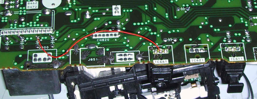
    MDS-JE440 Printed Circuit Board Photo -- Bottom View

  8. Drill holes in the rear panel for the new connector. This is a multi-step process:

    1. Measure the horizontal distance between the screw holes of the optical transmitter and receiver now soldered to the board.
    2. Measure the vertical distance from the top edge of the rear panel to (1) the center of the existing opening for the optical receiver and (2) center of its mounting screw hole.
    3. Using these horizontal and vertical measurements, mark the rear panel with the location of the new holes, center tap them, and drill them.

    (An alternate method is to thread a screw into the new optical transmitter and then begin to fit the board into place. As you bring the board into position you will be able to directly mark the rear panel locations for the new holes).

  9. Remove metal drill filings, fit the board into position, replace cables and screws.

  10. Cover any gap between the square connector and the round case opening with tape as shown below.

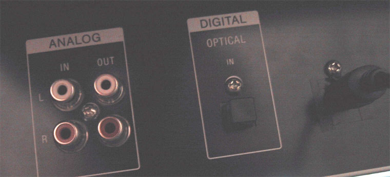
    MDS-JE440 Rear Panel

References

Service manuals:

Return to the MiniDisc Community Page.