First a note of warning! Although this project is cheap to build (only 6 small parts in all) it is definitely not for you if you've never held a soldering iron in your hands before. You also need to know the basics on working with electrostatic sensitive devices. Such as grounding yourself and your solder station. You will also need to do some pretty fine soldering work on a specific IC as well as make an 1/8th of a inch cut (with a sharp blade) to a metal trace located between two of its pins. Now if this all sounds too critical of a job for you, my advice is, don't sweat it and let someone who's use to doing this kind of work, do the work for you. If this no problem to you, you should then soon enjoy the addition of your new coaxial input.
O.K. I'll assume that if you are reading this, you're probably experienced enough to handle the job and complete it without a hitch (still you should follow the instructions exactly as they are laid out to you).
I've manage to complete the project in about an hour 1/2, including mounting the hardware (PHONO digital input jack and a mini switch) on the back of the units so I would guess that having step by step instructions to work with should help speed up the process somewhat.
First of all I must say that I've modified 3 MDS-JE510 units so far by adding such coaxial digital input and not only are they all still working great but IMHO are unquestionably more valuable now with these inputs installed then without them. Obviously one could buy or build an external digital signal converter to do the same job but doing it this way really solves the problem right at the source and save you money to boot!
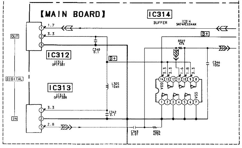
The circuit for the new coaxial input was taken from the JE510's service manual (AEP,UK,German models) at MINIDISC.ORG (also see reference section). These models use an extra IC ( Digital Data Selector-SN74HC153AN) in order to switch between their coaxial and optical inputs. For simplicities sake though, the mini-switch in this project will be serving this same purpose.
Circuit of your new coaxial input (Figure 2) will connect to Hex/Buffer IC 314 -SN74HCU04AN- (Figure 1) of your MDS-JE510 and use available I/O pins 12 & 13 of that IC. Although pin 12 is initially not connected to any other part of the circuit, pin 13 however comes joined (by a metal trace) to pin 14 VDD of that IC. That metal trace has to be physically (cleanly and carefully) cut in order for the new circuit to work . TIP: You may find that printing yourself a copy of this entire project (including all images) first, might be easier to work from then off of your monitor screen.
Remove top cover and back panel of your unit and disconnect 110 cord inside connector (push/clip-on type) CN301 in Figure A.
Pull out the three flat type cables that connects to the main board (pull straight out, not at an angle) unscrew board and unclip PCB holder at front left corner of main board (see Fig A).
NOTE: In all units I've worked on, these cables were white.
Remove main board and flip over (Foil side up) Oh yeah, clean up your bench first : )
Unsolder connection at jumper JW 117(Refer to Fig A and Fig 3) and pull jumper wire out.
Locate IC-314 (Fig A and Fig 6) and carefully cut copper trace in between pin 13 and 14 (make sure not to cut off any of the other fine copper traces nearby and MAKE SURE THAT YOU ARE WORKING ON THE RIGHT PINS BEFORE CUTTING!!! (Check pin number by turning board over) Use a continuity checker to make sure that your cut is clean and that connection is really broken off between pin 13 and 14 (very important step).
Still from the foil side, solder the 470K � Watt resistor between pin 12 and 13 of IC-314 (See Fig 6) TIP: Bend the resistor's legs so that they meet perfectly to pin 12 and 13. You can use a dab of crazy glue or piece of tape to hold resistor in place until soldered.
Cut 2 insulated wires (use different color for each) approx. 12" long. Strip � " of insulation off all ends and twist them together lengthwise.
Solder one wire to center leg of mini switch and insert (from the top of the PC board) the other end of the wire through hole "A" (now empty) of previous JW117 jumper location (refer to figure A and Fig 3) and solder.
Solder one end of the other 12" wire to one of the 2 remaining legs of the mini-switch and insert the other end of that wire through hole "B" and solder as well.
Cut 3 insulated wire approx. 6" long, strip ends and solder one of the 6" wire to the ground area indicated in Figure 6. (Heat up solder while inserting wire from top)
Screw main board back into place (Don't forget to push down on the board so as to "snap it" into place onto the plastic board holder) and reconnect the 3 flat type cables.
Take another 6" wire and solder one end to the 3rd remaining leg of the mini-switch, solder the other end to pin 12 of IC-314 FROM THE TOP SIDE OF THE IC. (Always double check pin location before soldering).
At this point you should cut-out the holes in the rear panel for your mini-switch and Phono jack . Although these hole placements are really (to an extent) a matter of preference, you can view where I have positioned mine for both installations in Figure 5. You can add stickers for referral to switch position as well, however, positioning the switch so that UP is COAXIAL and DOWN is OPTICAL makes it easy enough to remember.
Install the PHONO jack only (for now) on your rear panel and solder the 75 ohm � Watt resistor between PHONO jack's center lug and its metal shell casing or ground washer. Mount rear panel into place and solder ground wire coming from ground location in Figure 6. Make sure that no wires are caught between the main board and the panel (don't forget any screws).
Solder the last 6" remaining wire to the PHONO jack center lug and solder the 1K � Watt resistor at the other end.
Solder the 0.1 �F cap in series with that resistor insert shrink tubing over (optional) and solder the other end of the cap to pin 13 of IC-314. again (FROM THE TOP OF THE IC)
Install the mini switch in the hole that you've provided for it on the rear panel. I've install mine so that UP switches on the Coaxial Digital Input and DOWN switches the Optical one. To do the same, install the mini-switch so that you have the 12" wire (the one coming from point "B") sitting above the center leg of the mini-switch. (see Figure 4)
Tie-wrap any loose wires inside the unit and try it out using a Coaxial Digital source. If everything works out fine, tighten everything up and put your cover back on.
FOOT NOTE: While the mini-switch is set to coaxial digital input, you must have a cable (RCA type) connected between the coaxial digital output of the source unit and the PHONO jack (coaxial digital input) of your unit in order to avoid getting "DIN UNLOCK" message on your display. This also applies to your optical digital input of course.
You can BTW buy a proper video cable (75 ohm impedance) specifically design to handle such digital signal, although I have yet had any problems whatsoever using a regular RCA type audio cable. Eventually I might break down and buy that expensive fancy one at the video shop : ) I just can't put a date on it!
I apologies in advance for not having supplied any scanned picture of the MDS-JE510 unit in this project, however if you have any to share, please contact me and let me know. Also if you have spotted any mistake, omissions, typo errors or simply have come up with other ways in which to improve on this project, please feel free to contact me as well.
You can e-mail me at: [email protected]
Thanks,
A.J. Aylestock
[email protected]