 |
|
Differential (4-lead) outputs,
Class-D (digital or "1-bit") amplifiers,
and what they mean
Peter Rice
September, 2002
In the eternal quest for extended battery life, coupled with consumer demand for higher power drives to headphones, designers of MD, CD and MP3 players are introducing two main changes:
Let's talk about these two things separately, although they may both be present in a piece of equipment.
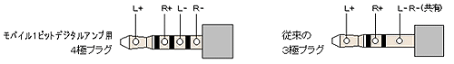
Conventional phones have 3-contact [right diagram] jacks (sleeve-ring-tip) where the sleeve is a common return for both ear pieces. The normal wiring is for a 3-core lead to be taken from the jack to one ear cradle, where one signal lead and a common drop down to the ear piece, and then the other signal plus the common go over the head to the other ear piece. Attempting to wire a 4-contact jack [left diagram] instead of the 3-contact jack on to this type of lead gives you the problem of what to do with the common wire. The other type of headphone lead brings a separate screened cable from each ear in a figure-of-8 cable down to the jack. These are obviously no problem to re-wire in a 4-contact configuration.
If you have a differential (push-pull) drive in your MD, what happens when you try to connect a 3-lead headphone (with the L- and R- signals shorted together) depends on the design of output stage. An un-protected design could burn out, especially if it is a "class-D" type (more on this below). The best that could be hoped for is that the stereo image would be impaired and the battery consumption greatly increased as the circuit poured difference-signal current into a short circuit.
There is a half-way system, where the common lead, instead of being ground, is the minus average of the L + R channels, and the L+ and R+ signals are arithmetically adjusted to subtract the opposite channel's minus signal. This keeps compatibility with standard phones, but only achieves something like 2x the output power.
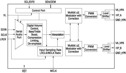
Now, the business of "1-bit DACs", "digital amps" and "class-D" output stages. Class-D is not new; I still have the remnants of a transistor switching amplifier I built from a Clive Sinclair kit in the early 1960s. It worked after a fashion, but radiated like crazy. "Class-D" is a generic term by extension from valve amps Class-A through Class-C, but is actually not related to that type of design. It covers pulse-width modulated systems, average-value systems and others where the required analogue output value is formed from a time-averaged version of a carrier waveform.
Sharp and others have been putting a lot of R&D time into this technology recently, not least because of the advent of digital signal processors (DSPs) and the availability of suitable power FETs. The real advantage of this type of design is that it can be nearly lossless, even when switching at many MegaHerz, by using high-frequency FETs that have on-resistance of only a few millohms. Sharp have coined "1-bit" for their version of the technology, and have released excellent hi-fi amps based on it (SM-SX series) as well as introducing it into their MD players.
A quick overview of the principle of operation is as follows: imagine a square wave switching between 0V and 3V (typical values in an MD output stage). Because the wave is symmetrical, the average value is constant at 1.5V. Now if you modify the waveshape to leave the 0-to-3V transitions in the same place but shift the 3-to-0V transitions backwards and forwards about their original position, the average value varies. Make the time-shifting vary with your input signal, then the average value of the output will be a representation of the signal. With digital source material (usually PCM encoded), you use a DSP to map the PCM encoding to time shifts in the waveform transitions. Most versions of the system shift both transition directions.
The final component in the chain is averaging (filtering) of the output. This is performed partly by chokes at the headphone output socket, partly by the mechanical characteristics of the headphones themselves, and partly by your ears.
So where is the "DAC"? Answer: it's not visible as a single component, but distributed through the reproduction chain. You could argue that the DAC is the algorithm that maps PCM values to time-shifts, although even these are quantised. Maybe it's the output averaging (filtering). It doesn't matter.
The "1-bit" name comes from there being only two levels (0V and 3V in our example), which in amplitude terms can be represented by the state of a single bit. All the signal information is contained in the times at which that bit changes state.
Actual designs are quite a bit more complicated than our simplified description. For example, it is necessary to compensate for changes in the rail voltage (the 3V of our example) due to battery ageing and, importantly, sudden loud outputs. So the rail voltage is fed back to the DSP, along with a digital value representing the setting of the "volume" control. Some sophisticated designs even use an ADC to feed back a digitised version of the actual filtered analogue output value to the DSP to form a negative feedback loop. This helps further to reduce distortion and to compensate for variable load characteristics.
Are there disadvantages? Well, yes, for some users. Despite extensive filtering, the headphone leads can still have high-frequency switching signals on them, and these often feed back into microphone leads and cause havoc in mixers and the like. Also, the phone output can't easily be used as a line output for connecting to hi-fi gear, again because there isn't a conventional audio signal on it.
To tie the two innovations together, the differential drive technique is equally applicable both conventional analogue signal chains and Class-D amplifiers. Differential stereo outputs would need 4 Class-D stages, the two for each channel having independent but opposite drives to the + and - leads of each earphone. In the absence of a signal, these both sit at half the rail voltage (1.5V in our example).
In terms of performance, the perceived sound quality at the ear of these newer configurations should not be any worse than conventional output stages. Indeed, they can probably run to higher sound pressure levels for given distortion figures. Also, with careful design, they can avoid using some troublesome components such as large-value capacitors, which are not only expensive, but have been known to give creeping degradation of sound quality with age.
Sounds great? When can we buy into this new technology? Right now - in fact, you probably won't have a choice by this time next year!